
Weld defects: inspection methods and reporting
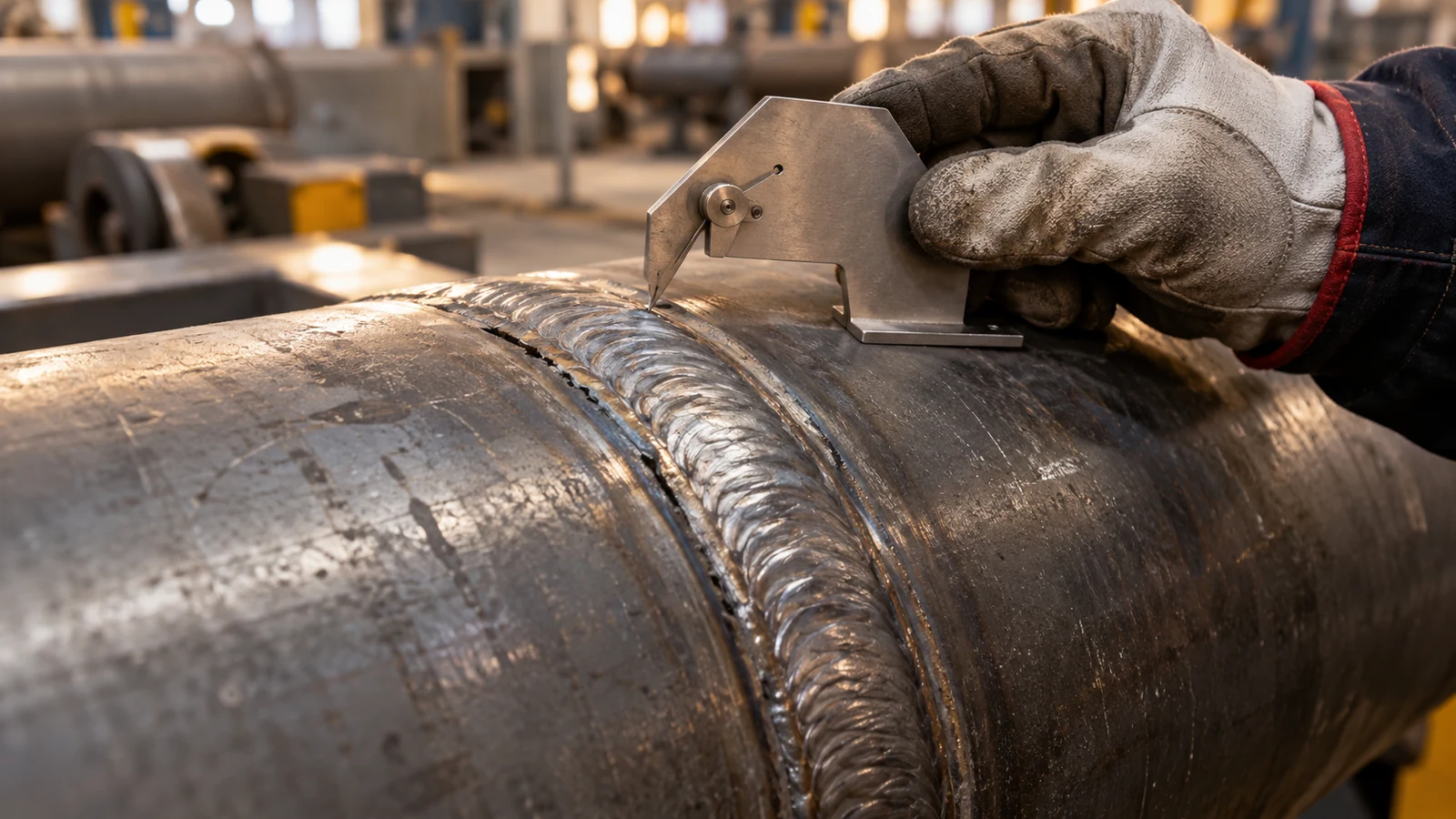
Weld defects are imperfections that fail the acceptance requirements for a particular joint. Cracks, porosity, inclusions, lack of fusion and undercut need different inspection approaches. A useful inspection report connects each finding to a weld location, the method used, the area actually examined and the agreed acceptance criteria.
Imperfection, indication or defect?
An imperfection is a departure from the intended weld. An indication is a response observed during testing that needs interpretation. A defect is an imperfection that is unacceptable against the applicable requirements. A photograph of a pore or a mark on an ultrasonic display does not, by itself, establish that a weld must be repaired.
ISO 6520-1:2007 provides a classification of geometric imperfections in fusion welds. Its categories cover cracks, cavities, solid inclusions, lack of fusion and penetration, shape and dimensional imperfections, and miscellaneous imperfections. Classification describes what was found; acceptance is a separate decision.
Common weld imperfections and what to investigate
- Cracks: linear separations in the weld or adjacent material. The cause and extent need investigation before a repair is specified; a surface photograph cannot establish the full depth.
- Porosity: gas cavities, which may be visible at the surface or enclosed within the weld. Check shielding, moisture and contamination. TWI explains the causes and prevention of porosity; surface appearance alone cannot establish the internal distribution.
- Solid inclusions: material such as slag trapped in the weld. Inter-run cleaning, joint access and welding technique should be reviewed alongside the inspection findings.
- Lack of fusion or penetration: incomplete joining at a sidewall, between runs or at the root. Joint preparation, access and welding parameters can contribute. TWI’s prevention guidance highlights preparation, parameters and technique.
- Undercut and poor profile: a groove at the weld toe, excessive reinforcement, overlap or misalignment. Measure the relevant geometry rather than deciding from appearance alone. TWI reviews geometric imperfections and their causes.
Agree the acceptance basis before inspection
ISO 5817:2023 defines quality levels B, C and D for imperfections in fusion-welded steel, nickel, titanium and their alloys, with B the most stringent. Its scope excludes beam welding and starts at 0.5 mm material thickness. The specified level belongs in the inspection plan; it should not be chosen after seeing the results.
The governing application standard, drawing, contract and responsible engineer determine the requirements for the joint. Record the applicable edition, quality level and any additional project requirements. Quality levels describe workmanship; they do not establish that an in-service component is safe for every load or operating condition.
ISO 17635:2025 guides selection of weld NDT methods and evaluation requirements. It distinguishes quality levels from method-specific acceptance levels: a quality-level letter is not a direct conversion for every NDT indication. Record both where required.
Choose a method for the material, geometry and suspected flaw
No single method finds every imperfection. The inspection plan should state the welds and percentage or length to examine, the technique, access requirements and evaluation criteria. Method descriptions below explain their purpose; they are not a claim that every technique is available on every Gridinta assignment.
- Visual testing (VT): examines accessible surfaces, preparation and weld profile. ISO 17637:2016 covers visual testing of fusion welds and can also be applied before welding. VT cannot establish the absence of embedded flaws.
- Penetrant testing (PT): reveals surface-breaking imperfections on suitable nonporous surfaces. Cleaning and surface condition affect the result.
- Magnetic particle testing (MT): suits ferromagnetic materials and detects surface and some near-surface imperfections. It is not a substitute for a method that examines the weld volume. TWI compares PT and MT.
- Ultrasonic testing (UT): investigates internal indications using a technique suited to the weld material, thickness and geometry. Beam direction, access and flaw orientation affect coverage.
- Radiographic testing (RT): creates an image of internal features. Geometry and flaw orientation affect detection, and radiation controls affect site planning. See TWI’s radiography overview.
Weld inspection reporting checklist
Use the following as a practical brief when agreeing an inspection report. It is a checklist for collecting traceable evidence, not a completed company report or a substitute for the reporting requirements of the chosen procedure.
- What was inspected: asset or component identifier, drawing and revision, weld numbers, material and thickness, joint type and a location reference that another person can find.
- Scope and timing: inspection date, production or in-service condition, weld lengths or areas covered, sampling basis and any required delay after welding.
- Method and setup: method, technique and procedure revision; test equipment and relevant verification records; surface preparation and conditions that affect the examination.
- Findings: a unique indication reference, location relative to a stated datum, measured dimensions, interpretation and an imperfection classification where applicable. Distinguish observations from suspected causes.
- Photographs and records: overview and close-up images with orientation and a scale where useful, linked to the weld and finding identifiers. Attach the relevant test records rather than an unexplained pass/fail label.
- Limitations: inaccessible areas, coatings, obstructed views, geometry, surface condition or other restrictions. State what was not examined and whether the agreed coverage was achieved.
- Evaluation: the acceptance standard and edition, level and project criteria; the result for each finding; the person responsible for evaluation and the inspection personnel’s relevant qualifications.
- Next steps: outstanding examination, engineering review, an agreed repair instruction or acceptance decision, responsible parties and the records needed to close the item. Link any repair and repeat inspection to the original finding.
From a finding to repair and closure
Separate the observation, the acceptance decision and the repair instruction. A suspected crack can require further examination to define its extent; an inaccessible area remains an inspection limitation. Neither should disappear into a general “passed” summary. Any repair method and subsequent testing must follow the applicable project requirements, with the original and follow-up records kept together.
Personnel qualifications and welding procedures are different records
ISO 9606-1 concerns qualification testing of welders for fusion welding of steels. ISO 14732 concerns operators and setters for mechanized and automatic welding. ISO 15614-1 concerns welding procedure tests. A procedure qualification is not a welder’s personal certificate; check the records that apply to the proposed work.
Planning inspection at height
Access must allow the inspection technique to work as intended. Agree surface preparation, equipment handling, coverage and rescue arrangements before mobilization. Rope access reaches the work area; it does not establish NDT competence or make an otherwise unsuitable technique reliable. Gridinta is listed as IRATA Full Operator member 6036/O.
For an actual job, discuss NDT and coating inspection, industrial welding and fitting and the rope access scope together. Send drawings, weld identifiers, material and thickness, required acceptance criteria, access restrictions and the reporting requirements.