
Wind turbine tower weld inspection and engineering escalation
Wind turbine tower weld inspection should establish the condition of defined structural joints and provide evidence for an engineering decision. Start with the tower design, weld map, inspection purpose and acceptance basis. Select non-destructive testing for the suspected damage and accessible geometry, then report what was actually examined. A visual finding, a surface-test indication and a structural assessment answer different questions.
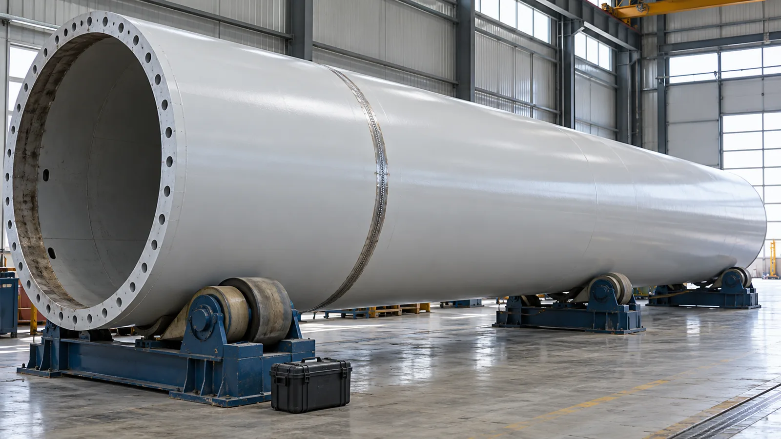
Define the tower detail and the inspection purpose
A steel tubular tower contains different welded details: circumferential seams between shell courses, longitudinal shell seams, shell-to-flange connections and local details around openings or attachments. Their geometry, access and role in transferring loads differ. A request to inspect “the tower welds” is therefore incomplete unless it identifies the joints, sides, coverage and reason for selecting them. A flange connection may also contain bolts; checking those bolts is a separate scope from examining the adjacent weld.
DNV-ST-0126 provides a structural framework for wind turbine support structures, including a contractual reference for design, construction, installation and in-service inspection. Its public overview is not a substitute for the project’s applicable edition and requirements. Establish which design documents, OEM instructions, inspection specification and engineering decisions govern the actual tower before selecting acceptance criteria.
Separate fabrication verification from an in-service investigation. The former asks whether construction meets specified requirements. The latter may investigate a reported crack-like indication, a known fleet issue, damage after an event or a question about continued service. Prior manufacturing records can provide a baseline, but they do not prove the present condition of an operating tower. For a wider maintenance scope, connect the weld package to the onshore turbine inspection checklist.
Why fatigue changes the question
Wind turbine support structures experience changing loads. For a welded detail, fatigue assessment concerns repeated stress and the potential for crack development, rather than appearance alone. TWI’s explanation of welded-joint fatigue describes the importance of local stress concentrations and crack growth at weld details. Consequently, an indication’s location and orientation matter alongside its measured size. A small visible mark cannot be classified as harmless using length alone.
The inspection team should describe observations without prematurely assigning a failure mechanism. A line in the coating may need investigation, but it is not yet proof of a steel crack. Conversely, an intact-looking exterior does not establish the condition of an inaccessible weld root. Record the suspected mechanism, the evidence supporting it and what remains uncertain so that engineering review starts from traceable observations.
Match the method to the question
- Visual examination: establish the joint location, visible condition, coating damage, corrosion and accessible weld profile. Record the lighting, access and surface limitations. Visual coverage does not establish the internal condition of the full weld thickness.
- Magnetic particle testing: consider it for surface or near-surface discontinuities in suitable ferromagnetic steel. The examination needs an appropriate technique and surface condition. It does not replace a volumetric examination when the concern lies within the joint.
- Ultrasonic examination: consider conventional or suitably qualified advanced techniques where internal indications or their extent need investigation. The procedure must address the joint geometry, material thickness, scan surfaces and relevant flaw orientations.
- Combined examinations: use complementary methods when one cannot answer the whole question. Document inaccessible areas and technical limitations explicitly rather than describing a partially examined joint as fully inspected.
The method principles are described in TWI’s guidance on magnetic particle testing and manual ultrasonic testing. The procurement task is to ask the responsible NDT specialist to demonstrate how the proposed procedure addresses this tower detail. A method name, instrument model or access qualification alone does not demonstrate suitable examination coverage.
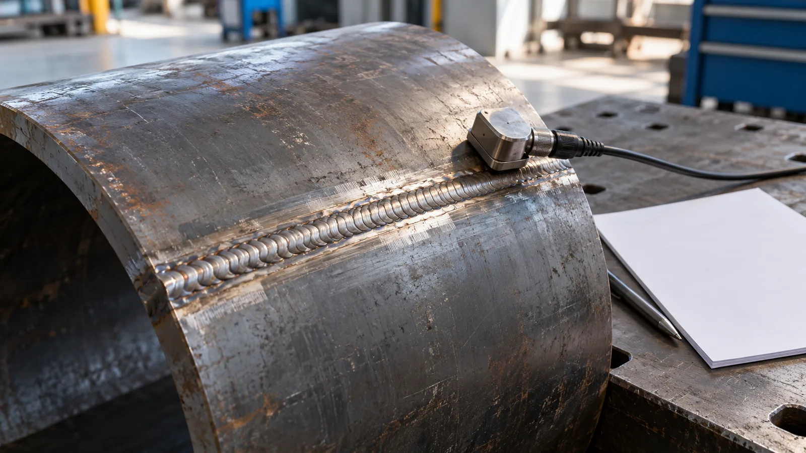
Surface condition and access belong in the inspection plan
A public MISTRAS tower-weld case study describes in-service ultrasonic inspection of circumferential tower welds for suspected cracking. It illustrates a defined inspection problem, not a universal prescription for every tower. For your own scope, identify whether the required scanning surfaces can be reached and whether the coating condition permits the proposed technique. Any preparation or coating removal needs to be agreed, with restoration included where required.
Plan the work location as carefully as the test. Internal platforms, cables, ladders and the tower wall can constrain probe movement and visibility. External access has a different work envelope. Confirm turbine operating status, isolation arrangements, permitted access, equipment handling and rescue provisions through the site’s work system. Reaching a weld does not guarantee sufficient space to examine it using the intended procedure.
Evidence to collect for an engineering review
- Asset and joint identity: turbine identifier, tower section, weld reference, elevation and a repeatable circumferential position convention. Include an overview image or drawing so a second team can relocate the finding.
- Inspection basis: purpose, procedure and revision, applicable criteria, personnel qualification relevant to the method, equipment identification and required calibration or verification records.
- Actual coverage: inspected side and length or area, scan directions where relevant, inaccessible regions, surface preparation, coating condition and any departure from the planned scope.
- Finding record: unique identifier, original data, annotated images, measured position and dimensions, method of sizing and stated uncertainty. Keep observations separate from interpretation.
- Action and closure: reviewer, disposition, further examination or monitoring required, operating decision reference and the evidence needed to close the finding.
This package should join the turbine’s existing inspection history. Consistent location references help distinguish a new observation from a previously reported one. If the later report uses a different technique or sizing method, document that difference before describing growth. For terminology and general report structure, see weld indications, defects and inspection reporting.
Escalate findings without inventing universal limits
A crack-like indication in a load-carrying joint should enter the agreed escalation process promptly. The responsible engineering authority determines whether additional confirmation, operating restrictions, repair or monitoring is required. That decision may need joint drawings, material information, loading history, previous repairs and the inspection’s detection and sizing limits. The inspector’s evidence supports the decision; it does not replace that assessment.
Do not apply a generic acceptable crack length or a service interval copied from another turbine. Manufacturing quality acceptance and the engineering assessment of an in-service indication serve different purposes. If monitoring is selected, obtain a written method, review date and trigger for reassessment. If repair is selected, use an approved repair plan with subsequent examination and a documented release decision.
Common questions
Frequently asked questions
Is an external photograph enough to clear a tower weld?
Can every tower weld be examined with the same ultrasonic procedure?
Does a crack-like indication automatically mean a weld repair?
How often should tower welds be inspected?
Sources and scope
Public sources reviewed on 25 October 2026: DNV-ST-0126 overview, TWI on welded-joint fatigue, TWI magnetic particle testing, TWI ultrasonic testing and MISTRAS tower-weld inspection case. The planning checklist is editorial guidance, not a tower-specific procedure, acceptance standard or fitness-for-service decision.