
How Bolt Tensioning and Torque Checks Keep Wind Turbine Joints Tight
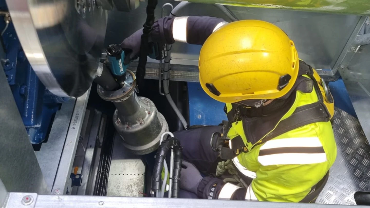
A wind turbine holds together with thousands of preloaded bolts, and they only work while the preload stays in them. Most OEM programmes re-check all critical bolting after about 500 operating hours. After that, annual or semi-annual services re-check a sample of at least 10%, and if one sampled bolt fails, every bolt on that flange is checked. Large flange and foundation bolts are usually tensioned hydraulically. Smaller joints are torqued.
As of October 2026. Intervals and methods vary by turbine model; your OEM manual and design documents take precedence over the general practice described here.
Which bolted joints on a wind turbine matter most
Every turbine has well over 1,000 bolts, according to ORE Catapult (2022), and one tool maker puts some new platforms at 6,000 to 8,000 bolts from M27 to M80. Not all of them carry the same risk. The joints below carry the main structural loads, and a failure in any of them can bring down a blade, a nacelle or a tower.
| Joint | What it holds | Published example | Usual tightening |
|---|---|---|---|
| Foundation anchor bolts | Tower base to the concrete foundation through an anchor cage | Foundation base bolts are typically tensioned (Windpower Engineering, 2017) | Hydraulic tensioning |
| Tower ring flanges | Tower sections to each other and to the nacelle yaw bearing | High-strength HV bolt sets of M36 and larger, up to M64 or M72 at large offshore tower bases (Liu et al., 2016); a worked L-flange example with 80 x M36 grade 10.9 bolts (Pedersen, Wind Energy, 2017) | Hydraulic tensioning or torque, per OEM |
| Blade root | Blade to pitch bearing through inserts or T-bolts | 192 x M48 bolts on a 6.6 m root in a 22 MW reference design study (DTU, TORQUE 2026) | Tensioning, on site |
| Pitch and yaw bearings, yaw brakes | Bearings to hub and bedplate; brake callipers to the yaw ring | 12 to 18 torqued brake housings on passive yaw systems (Valley Forge whitepaper, 2023) | Mostly torque |
| Main bearing, main shaft and hub | Drivetrain to bedplate and rotor to shaft | Sizes vary by platform; public data is thin, so use the OEM manual | Torque or tensioning, per OEM |
| Offshore monopile to transition piece | Tower and turbine to the foundation | 84 x M72 grade 10.9 bolts per foundation at one Belgian wind farm (Parkwind, 2020) | Tensioning or tension-control fasteners |
Torque or tension: how the two methods differ
Both methods aim at the same thing: a set clamping force, or preload, in each bolt. They get there differently.
- Torque tightening turns the nut against friction. As Nord-Lock explains, around 90% of the applied torque goes into friction under the nut and in the threads, so small changes in lubrication or surface condition shift the resulting preload. A torque value tells you what the tool did, not the force in the bolt.
- Hydraulic tensioning stretches the bolt directly with a hydraulic tool sitting over the nut, then runs the nut down and releases the pressure. Friction plays a much smaller role. Some load is lost when the tensioner is released, and that loss has to be planned for. The bolt also needs enough thread above the nut for the tool; Atlas Copco gives at least one bolt diameter and recommends tensioning for bolts above M48.
The German bolting guideline VDI 2230 expresses tool accuracy as a tightening factor: the ratio between the highest and lowest preload a method produces. The values below are taken from the Wurth technical handbook, which reproduces the VDI 2230 table.
| Method | Tightening factor | Approximate preload scatter |
|---|---|---|
| Ultrasonic elongation-controlled tightening | 1.05 to 1.2 | plus or minus 2% to 10% |
| Hydraulic tensioning | 1.2 to 1.6 | plus or minus 9% to 23% (lower for long bolts) |
| Yield- or angle-controlled tightening | 1.2 to 1.4 | plus or minus 9% to 17% |
| Torque wrench, torque set by testing on the actual joint | 1.4 to 1.6 | plus or minus 17% to 23% |
| Torque wrench, friction estimated | 1.6 to 2.5 | plus or minus 23% to 43% |
Two practical points follow. First, a torque check on a bolt that was tensioned does not measure its preload. Second, specifying the method, lubricant and sequence matters as much as the target value. Flange bolting is commonly brought up in stages; Wind Systems describes a 30%, 70% and 100% torque progression.
Why bolts lose preload
Preload does not stay where it was set. The main mechanisms are well documented:
- Settling. Contact surfaces under the nut, in the threads and between flange faces flatten slightly in the first loading cycles. Early research at the University of Hannover by Schaumann and Seidel (FKM, 2002) quantified this settling in ring-flange tests.
- Release loss after tensioning. In full-scale tests on M48 L-flange bolts published in 2026, Shakeri and co-authors found that preload of about 95% of yield fell to about 79% once the tensioner was removed, and that cyclic loading sped up relaxation. On a blade-root test rig matching a 10 MW turbine, Han et al. (2025) measured an 11% to 16% preload drop on M36 bolts during the fastening process itself.
- Flange imperfections. Gaps and out-of-flatness between flange faces change how load passes through the bolts. The tower standard IEC 61400-6 has been amended because its preloading rules proved insufficient in practice, as Marc Seidel describes in Stahlbau (2025). The amendment adds tightening procedure requirements and a method for preload losses.
- Corrosion and grout damage. Corroded washers and nuts on foundation anchor bolts can lose tension, and anchor bolts lose some tension over time, according to Wind Systems (2019).
The consequence of low preload is fatigue. A bolt that stays fully preloaded sees only a small share of each load cycle. A loose bolt sees much more of each cycle, so fatigue cracks can start long before the design life.
Wind turbine bolt torque and tension checks over the turbine's life
Re-check programmes follow a common pattern, with details set by each OEM and design engineer.
| Stage | Typical scope | Source |
|---|---|---|
| Installation | 100% tightening to procedure, in staged passes, with records per bolt | Wind Systems, 2012 |
| First service, about 500 operating hours | 100% re-check of critical bolting from base to blade; full re-tension of foundation anchor bolts | Wind Systems, 2010; Wind Systems, 2019 |
| Annual or semi-annual service | Re-check of at least 10% of tensioned bolts, marked so the sample rotates; some OEMs require 100% on critical joints | Wind Systems, 2012 |
| Sample failure | If one sampled bolt is below the check value, check all bolts on that flange | Wind Systems, 2012 |
| Foundation anchor bolts | Tension test of a random 10% about every other year, at about 10% below initial tension; any nut that turns or lifts means re-tensioning the whole foundation; many operators fully re-tension every 5 years | Wind Systems, 2019 |
| Recurring inspection, Germany | At least a visual and looseness check of preloaded bolts | DIBt guideline, section 15.2 |
| Beyond design life, Denmark | Annual visual check of bolts, foundation and anchor bolts; retightening per the manual | Danish order no. 648/2023, annex 4 |
Field data supports moving from fixed calendars to evidence. Belgian operator Parkwind tracked 4,200 M72 bolts on 50 offshore monopile-to-transition-piece flanges. About 5%, then 3%, of bolts needed retightening in early campaigns, and the share of loose bolts fell after each round to about 1%. The authors proposed an interval of about 500 days and sampling at least 30% to 50% of turbines. That is one offshore fleet with one fastener system, but it shows how check data can justify a longer or shorter interval.
The DIBt guideline sets the inspection frame for German turbines; our article on turbine inspection intervals lists the other checks that sit alongside bolt work.
Ultrasonic bolt load measurement and load indicators
Torque and tension checks only tell you whether the nut moves at a set value. Measuring the bolt itself gives a direct reading of preload.
- Ultrasonic measurement. A transducer on the bolt end measures the time of flight of a sound pulse, which changes as the bolt stretches. ASTM E1685 is the standard practice for measuring bolt length change this way. VDI 2230 gives ultrasonic control the best tightening factor in the table above. A baseline reading on the unloaded bolt makes later readings far more reliable.
- Load-indicating washers and bolts. Direct tension indicators to EN 14399-9 cover only sizes M12 to M36, so they do not fit most tower flange and foundation bolts. Load-indicating bolts with built-in gauges are available for larger sizes; one maker quotes accuracy of plus or minus 5% (Windpower Engineering, 2009).
- Faster inspection tools. A Danish ultrasonic tool maker claims accuracy better than 5%, over 100 bolts an hour and a cost of 3 to 4 euros per bolt (Energetica India, 2021). ORE Catapult describes bolt checks as the biggest scheduled maintenance task for operators. Treat vendor figures as claims until tested on your joints.
- Visual monitoring. Paint or witness marks across nut and flange show rotation at a glance. Researchers have tested camera systems that detect loosening from marked bolts (Wind Systems, 2021).
What good bolt documentation looks like
A bolt check you cannot trace is hard to defend to an inspector, insurer or buyer. Ask for:
- a bolt map per joint, numbering each bolt and showing which were in this sample;
- the procedure used: method, target torque or pressure, lubricant, sequence and passes;
- tool identification with valid calibration certificates (torque tools are commonly calibrated every 12 months or 5,000 cycles under ISO 6789, as tool maker Elora summarises; Wind Systems notes most OEMs accept at most 4% tool error);
- results per bolt, including nuts that turned, broken or missing bolts and corrosion;
- nonconformities and what was done: extension to 100% of the flange, bolt replacement, engineering referral;
- photos of witness marks, flange gaps and rust staining for comparison next time.
Failure signs owners should not ignore
- Rust streaks running down from a flange, which suggests water ingress and corrosion at the joint.
- Broken or shifted witness marks, or nuts that turn at the check value.
- Visible gaps between flange faces, especially on one side.
- Broken or missing bolts, or cracked bolt heads.
- Cracked grout, water pooling or concrete cracking around foundation anchor bolts.
- Unusual noises, or vibration alarms with no other explanation.
The worst case is well documented. On 24 December 2015 a turbine tower at Lemnhult in Sweden collapsed after the flange between its first and second sections failed. The Swedish Accident Investigation Authority (report RO 2017:01) found bolt fatigue caused by too little pretension. It linked this to wet weather affecting nut lubricant during assembly, tools not maintained to the standard, inexperienced assemblers and settlement not being accounted for. The wind farm had earlier problems with loose and broken bolts that were not reported. At the blade root, low preload in one bolt shifts load to its neighbours, which can end in the blade separating from the hub, as ONYX Insight's failure atlas describes. A published ASM failure analysis of a 600 kW blade detachment named insufficient bolt preload as the root cause.
For other common faults, see the most common failures in wind turbines.
Access and safety for bolt work
Most bolt work happens inside the turbine: in the tower base or foundation basement, on tower platforms, in the nacelle and in the hub. Each has hazards that need planning. A basement vault can be a permit-required confined space, as Occupational Health and Safety magazine notes for US sites. Hydraulic tensioners run at high pressure; one maker lists 1,500 bar for its foundation bolt tensioners. Torque tools can weigh up to 40 kg, according to inspection robot developer Innerspec. Lifting and hose-handling plans matter as much as the bolting procedure.
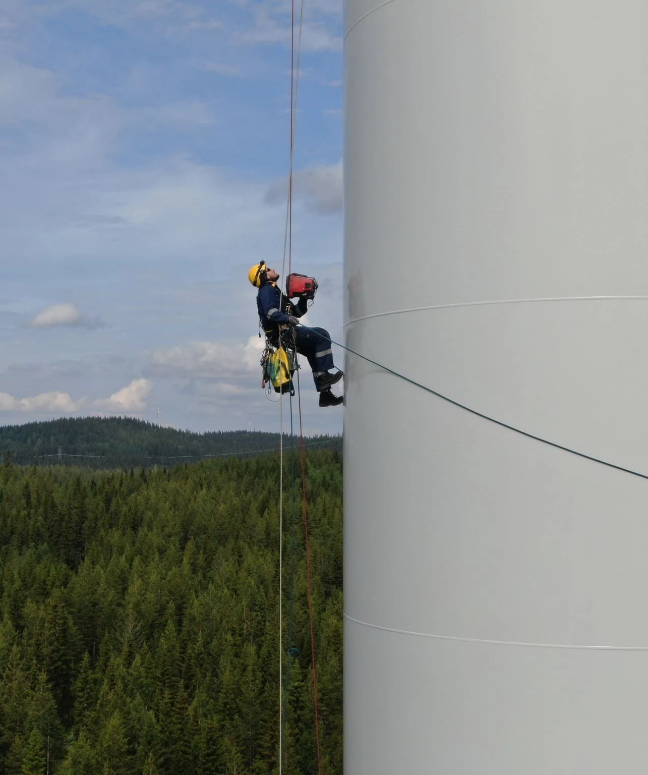
Rope access adds options outside the tower: inspecting external flange seals and coating, cleaning rust staining back to sound metal, and reaching areas without platforms. For the inspection methods that can follow a finding, see rope access NDT methods and their limits. Offshore foundations bring extra steps, covered in offshore wind foundation inspection.
Planning bolt work across a fleet
- Pull the bolt specification for each joint from the OEM manual and design documents: size, grade, method, target values and check values.
- Agree the sample rule and the escalation rule (for example, 10% sample, full flange on any failure) before mobilisation.
- Bundle bolt checks with other inspection items to make the best use of each access setup.
- Track results per flange over time, and use them to adjust intervals with your engineer, as Parkwind did.
- After the warranty ends, check that the new provider has the bolt specifications and tools; our end-of-warranty inspection guide covers the handover.
For budgeting, bolt work sits within scheduled maintenance; see wind turbine maintenance cost per year and the task list in our onshore inspection and maintenance checklist. Ageing turbines need closer attention; see life extension inspections.
Where Gridinta fits
Bolt tightening is listed as a core duty in Gridinta's wind turbine technician job description, alongside gearbox oil exchange. Tower bolt tightening is part of the structural maintenance on our onshore wind services page. As an IRATA member company (6036/O), we can combine internal bolt work with external rope access checks. We work to your OEM specification and hand back per-bolt records.