
Wind Turbine Coatings: What Each Component Needs
Wind turbine coatings are several systems, not one. Steel towers and cast hubs carry multi-coat anticorrosion paint matched to an ISO 12944-2 corrosivity category. Flange bolts may use hot-dip galvanising or zinc flake coatings specified for the joint. Nacelle covers and blades have gelcoat or polyurethane finishes, and offshore foundations add cathodic protection and corrosion allowance where paint alone cannot cope.
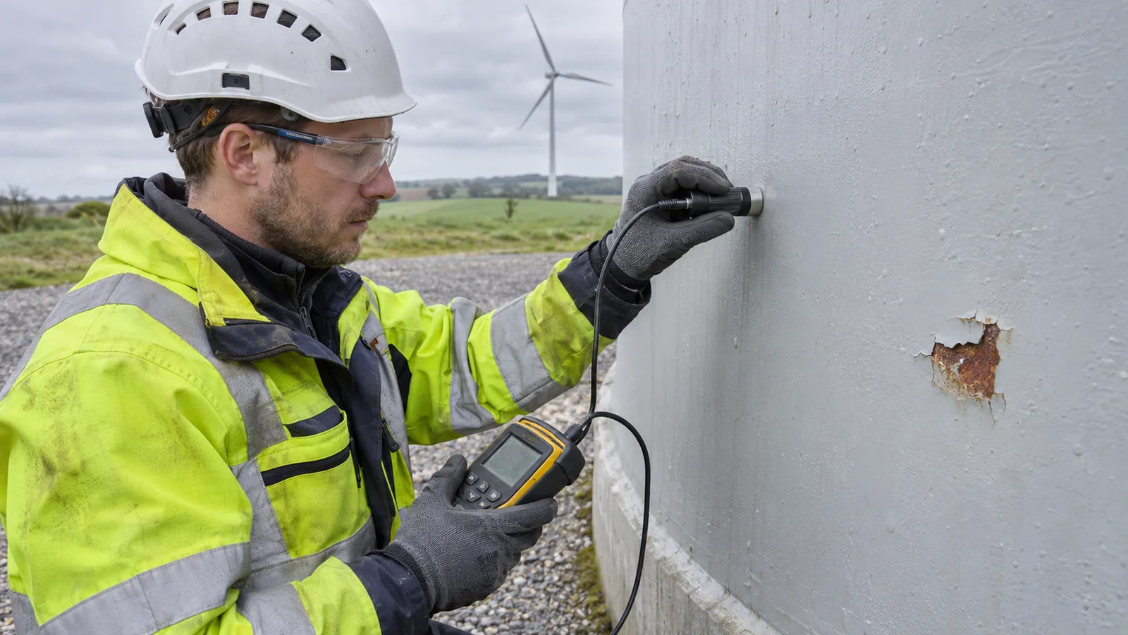
Which coating protects which part of a wind turbine
A turbine combines three material families. Carbon steel in the tower, transition piece (TP), monopile and flanges needs an anticorrosion coating and, below water, cathodic protection (CP). Cast iron or cast steel in the hub is painted. Glass-fibre composite in the blades, nacelle cover and spinner needs a finish against weathering and erosion, not an anticorrosion system.
Scroll horizontally to see all table columns.
| Component | Exposure | Typical protection | Main failure mode | Inspection focus |
|---|---|---|---|---|
| Tower exterior | C2–C5 onshore; CX offshore | Zinc-rich or metallised primer, epoxy, polyurethane finish | Handling damage; rust at edges and welds | Rust, blister and flaking ratings by section |
| Tower and TP interior | Sheltered but damp; C4–C5 offshore | Interior system; dehumidification offshore | Rust where condensation collects | Flange tops, platforms, cable entries, base slab |
| Flanges and bolts | Crevices, condensation, spray | Hot-dip galvanised or zinc flake bolts | Zinc consumed, then red rust; tool damage | Rust bleeding from the flange gap |
| Nacelle cover and spinner | Sunlight, rain, wind-driven water | Glass-fibre composite with gelcoat or paint | Cracked or chalked finish; leaking joints | Cracks at fixings and hatches; water inside |
| Hub | Inside the spinner; humid | Paint on cast iron or cast steel | Rust at bolt heads; damaged paint | Bolt heads, casting edges, earlier repairs |
| Blades | Rain, hail, sunlight, tip speed | Gelcoat or polyurethane topcoat; LEP | Leading-edge erosion | Leading edge on the outer span |
| Onshore tower base | Standing water, splashback | Coated base section; sealed grout joint | Rust at the base flange and anchor nuts | Drainage, sealant, grout, bolt caps |
| Splash zone and TP | Wet–dry cycling, impact | Qualified offshore system plus corrosion allowance | Impact damage; coating breakdown | Defect map by elevation; wall thickness |
| Submerged monopile | Im4 seawater | CP; coating optional | Anode depletion; coating disbondment | CP potential survey; anodes |
| Monopile interior | Tidal water exchange, low oxygen | CP or corrosion allowance; sealed deck | Waterline pitting; microbial corrosion | Seals, gas, waterline thickness |
Use the table to plan a survey, not to write a specification: the governing specification, the manufacturer’s manual and a site corrosivity assessment take precedence. When a survey turns into repair, Gridinta’s rope access painting and coating services cover surface preparation, touch-up and repainting of towers and offshore steel, with preparation grades and inspection records agreed first.
Corrosion zones on onshore and offshore turbines
ISO 12944-2:2017 grades atmospheric corrosivity from C1 to CX and immersion from Im1 to Im4; our guide to ISO 12944 corrosivity categories gives the full tables. On a turbine, one structure spans several categories. The standard’s examples put rural sites with low pollution in C2, urban and industrial air in C3, coasts with moderate salinity in C4 and coasts with high salinity in C5, so two towers of the same model can need different systems depending on how close they stand to the sea.
Exposed offshore steel is commonly specified for CX, the extreme atmospheric category; sheltered components and interiors need their own exposure assessment. A 2024 review by Syrek-Gerstenkorn and Paul places internal offshore surfaces in C4 to C5 and notes that VGBE-S-021 (2023) allows C3 where air conditioning holds relative humidity below 60 %. Immersed steel in sea or brackish water with cathodic protection falls in Im4, the immersion category covered by ISO 12944-9. The splash zone between them is the hardest band to protect.
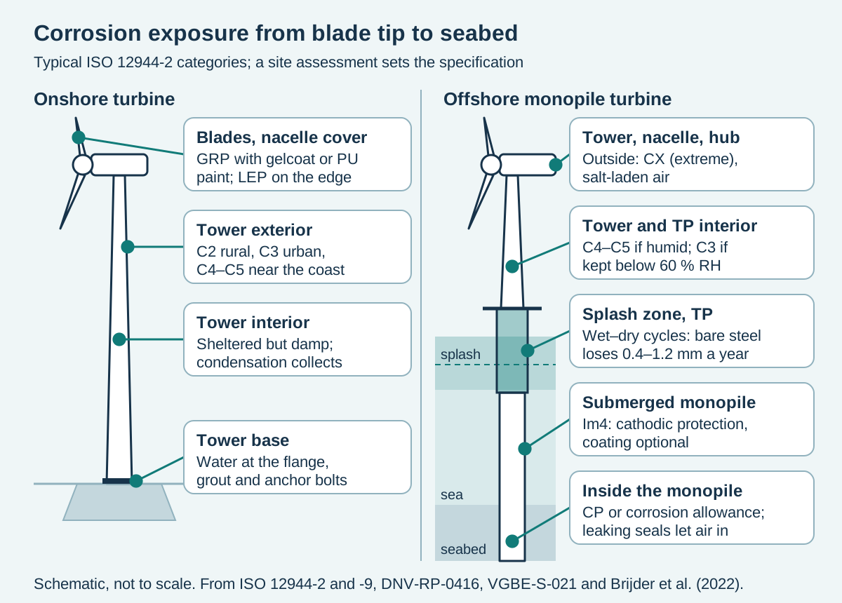
In ISO 12944-1:2017, durability is the expected time to the first major maintenance painting, a planning figure rather than a guarantee. ISO 12944-9:2018 qualifies offshore systems for the high range only, 15 to 25 years, and NORSOK M-501:2022 also advises high durability. For a structure intended to operate beyond the coating’s specified durability, include inspection access and maintenance painting in the life-cycle plan.
Tower exterior, the largest painted surface
The usual atmospheric system is a stack of epoxy layers finished with polyurethane. Syrek-Gerstenkorn and Paul found that ISO 12944, NORSOK M-501 and VGBE-S-021 all recommend a sacrificial first layer: a zinc-rich primer, hot-dip galvanising or a thermally sprayed zinc or zinc–aluminium coating. The draft ISO/CD 25249-2 names the same two routes for offshore wind tower steel: thermally sprayed metal, as sprayed, sealed or overcoated, or a zinc-rich, epoxy and polyurethane paint system.
Compare coating options over the planned service period. Include surface preparation, application, access, weather standby and future maintenance campaigns in the estimate. Offshore mobilisation can change the economics substantially, so use project-specific quantities and access assumptions when comparing a paint system with a metal-spray duplex system.
Most tower coating failures start with a defect rather than age. Brijder and colleagues (2022) note that accidental scratches can start corrosion much earlier than expected, and the 2024 review blames many failures on poor surface preparation, poor environmental control or the wrong system for the zone. Look first at erection damage, edges, welds, door frames and bracket attachments; our article on why industrial coatings fail explains the mechanisms.
Record ratings, not adjectives: rusting under ISO 4628-3, blistering under ISO 4628-2, cracking under ISO 4628-4 and flaking under ISO 4628-5, each with its elevation and side. Drones can screen the shell, but adhesion, film thickness and the steel under a blister need close access. Treat rust at a weld with suspicion, since cracks bleed rust too, and follow the tower weld inspection and escalation route before anyone paints over it.
Tower and transition-piece interiors
An onshore tower interior is sheltered but not dry. ISO 12944-2’s interior example for C2 is an unheated building where condensation can occur, which fits an unheated steel tower. Condensation gathers on flange tops, platform supports, cable entries and the base slab, so inspect there first, along with leaks from nacelle and door seals.
Offshore interiors see more salt and humidity, so plan them for C4 to C5 unless they are dehumidified. If a design uses dehumidification to justify a lighter C3 system, the dehumidifiers become part of the corrosion protection and need their own maintenance plan and humidity records.
Flanges, bolts and the galvanised fastener question
Tower and TP sections are joined by bolted ring flanges. A review by Lochan, Mehmanparast and Wintle (2019) notes that high-strength preloaded bolt assemblies to BS EN 14399-4, property class 10.9, are recommended for these joints, and that offshore bolts are commonly hot-dip galvanised. It also records the trade-off: hot-dip galvanising can affect fatigue performance, and the joint design must account for the specified assembly.
Zinc flake is the main alternative. ISO 10683:2018 covers zinc flake systems for fasteners, with or without top coat and lubricant, and notes their use on fasteners of 1,000 MPa and above to avoid internal hydrogen embrittlement; class 10.9 sits at that threshold. The choice belongs to the turbine designer and bolt supplier, because coating and lubricant change thread friction and so the torque needed for a given preload.
For maintenance, replacement bolts must match the specified coating and lubricant, or the torque and tension values in the service manual may no longer hold. Bolt checks are also the moment to inspect the coating: zinc corrosion turning to red rust, tool damage on nuts and washers, and rust bleeding from the flange gap, which means water is entering the joint. Our guide to bolt tensioning and torque checks on wind turbines covers the preload side.
Nacelle cover, hub and spinner
Many nacelle covers and spinners are glass-fibre composite mouldings, often sandwich laminates; DTU researchers used that build in 2025 when testing recycled-fibre laminates for nacelle covers. Their coating problems are weathering problems: a chalked or crazed finish, cracks around fixings and hatches, and leaking joints that drip onto the machinery. Use repair products approved for the substrate and original finish; a steel anticorrosion specification cannot establish suitability for a composite cover.
The hub is a large casting, and the draft ISO/CD 25249-2 explicitly covers cast iron and cast steel components of the rotor–nacelle assembly. Inside the spinner it is shielded from rain but not from humid, salty air. On hub entries, check bolt heads, casting edges and earlier repairs, using the same ISO 4628 ratings as on the tower.
Blade topcoat, gelcoat and leading-edge protection
Blade finishes are applied in two ways. A University of Strathclyde review by Keegan, Nash and Stack (2013) describes in-mould coatings, usually similar to the laminate matrix such as epoxy or polyester, and post-mould coatings painted or sprayed on afterwards, where more elastic materials such as polyurethanes can be used. Many blades combine both, and the industry calls almost any blade surface layer a “gelcoat”, so confirm the actual system with the blade manufacturer before a repair.
The leading edge fails first; the same review cites operators finding leading-edge erosion after only two years in service. Leading-edge protection (LEP) is a separate layer, supplied as tape, shells or liquid coating with its own rain-erosion tests, and our guide to choosing leading-edge protection systems compares them. Use the blade-approved finish and LEP specification rather than substituting a tower or foundation coating system.
Onshore tower base and foundation interface
IEC 61400-6:2020 sets the design requirements for onshore towers and foundations, counts maintenance among the life-cycle issues that affect structural integrity, and lists the ISO 12944 series as a normative reference. In service, the base is where water ends up, and the bottom flange, the grout joint beneath it and, on anchor-cage foundations, the anchor bolt nuts all sit in it. At each annual inspection, check:
- Drainage: water should run off the pedestal, not stand against the shell.
- Grout and sealant: cracked or missing sealant at the flange-to-grout joint, and grout cracks that let water under the flange.
- Anchor bolts: nuts, washers and protruding threads, and whether protective caps are intact and filled as specified.
- Bottom section coating: rust and blistering ratings on the lowest part of the shell, inside and out.
- Escalation: grout and concrete repairs are civil works, and corroded anchor bolts can affect preload, so refer both to the foundation designer before painting.
Offshore transition piece, splash zone and monopile
Offshore support structures combine coatings, CP and corrosion allowance, extra steel thickness that is allowed to corrode. DNV-RP-0416 (edition 2016-03, amended 2021-10), the recommended practice for wind turbine corrosion protection, focuses on these structures, and each zone uses a different mix.
Splash zone and transition piece
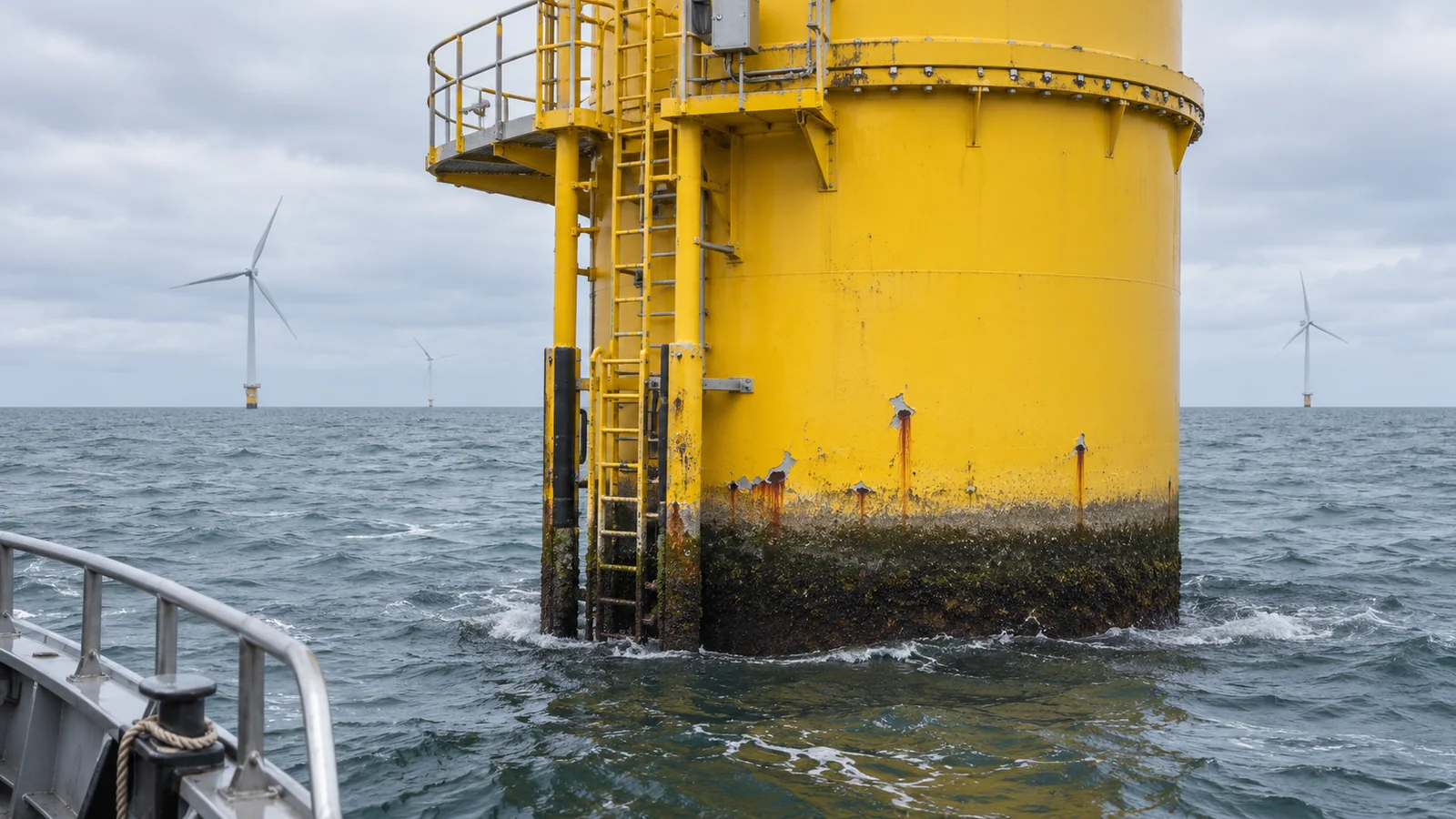
Bare carbon steel in the splash and tidal zone can lose 0.4 to 1.2 mm a year, according to Brijder and colleagues, and CP is not effective at all times in parts of the zone. Designers therefore add corrosion allowance: as summarised in the 2024 review, DNV-RP-0416 sets minimum design rates for splash-zone primary steel of 0.3 mm a year outside and 0.1 mm a year inside where seawater stays at or below 12 °C, and 0.4 and 0.2 mm a year in subtropical and tropical seas.
Offshore coating systems are qualified by testing. Under ISO 12944-9, NORSOK M-501 and VGBE-S-021, atmospheric systems pass at least 4,200 hours of cyclic ageing; splash-zone systems add cathodic disbondment tests, and NORSOK and VGBE an impact test. ISO 24656:2022 does not recommend zinc-rich primers in the immersed, tidal and splash zones, where thermally sprayed aluminium is one alternative. Expect early maintenance: Brijder and colleagues cite DNV-RP-0416 as expecting only about 10 years of splash-zone coating life for NORSOK M-501 system 7A.
Where the transition piece uses a grouted overlap with the monopile, inspect the connection and seals against the as-built design. Khodabux, Causon and Brennan (2020) discuss European projects where grout failures allowed seawater into the connection and contributed to unexpected corrosion. Confirm the connection type, protective system and access points for the actual structure. Our splash-zone corrosion inspection and repair guide sets out the repair sequence, and the offshore wind foundation inspection guide covers boat landings and welds.
Submerged steel and cathodic protection
Below the splash zone, protection shifts to CP. As summarised in the 2024 review, DNV-RP-0416 requires external submerged surfaces to be cathodically protected and treats coating as optional, a way to cut current demand. Current comes from aluminium or zinc anodes designed to DNV-RP-B401 (edition 2021-05) or from an impressed current system, and ISO 24656:2022 covers design, residual-life assessment, retrofit and monitoring. Plan underwater maintenance around CP potential surveys, anode condition and the coating condition required by the design; specify any coating repairs for the actual underwater exposure and access method.
Inside the monopile
Early monopiles were designed as sealed compartments where corrosion would stop once the trapped oxygen was used up. Surveys summarised by Khodabux and colleagues found that seals and airtight platforms leaked, letting oxygen in, while water inside the pile rose and fell with the tide. Where a compartment does stay sealed, the water turns anaerobic and corrosion can release hydrogen sulphide. DNV-RP-0416 specifies CP or corrosion allowance inside, with or without coating. Treat the space below the airtight deck as a confined space with a gas hazard.
Standards for wind turbine coatings, as of November 2026
Scroll horizontally to see all table columns.
| Document | What it covers on a turbine | Status |
|---|---|---|
| ISO 12944-2:2017 | Corrosivity categories C1–CX and Im1–Im4 | Current; revision at working draft |
| ISO 12944-9:2018 | Offshore paint systems for CX and Im4; high durability; -20 °C to +80 °C | Current; confirmed in 2025, revision planned |
| NORSOK M-501:2022 | Coating selection, preparation, application and inspection offshore | 2022 edition |
| VGBE-S-021 | Corrosion protection of offshore wind structures, Parts 1 to 3 | 2023 edition |
| DNV-RP-0416 | Coatings, CP and corrosion allowance, mainly offshore support structures | Edition 2016-03, amended 2021-10 |
| ISO 24656:2022 | CP of offshore wind structures, inside and outside | Current |
| IEC 61400-6:2020 | Onshore towers and foundations; cites ISO 12944 | Current |
| ISO/CD 25249-1 and -2 | Future ISO standard on offshore wind corrosion protection | Committee draft |
None of these is law on its own: a contract, design basis or certification scheme makes one binding. Name the edition in the specification, because ISO 12944-1, -2 and -9 and ISO 8501-1 are all under revision.
Touch-up, overcoat or full refurbishment?
ISO 12944-1:2017 defines three levels of maintenance. Spot repair restores local defects, including their surface preparation. Partial maintenance is spot repair followed by at least one coat over the whole area. Full maintenance removes the entire paint system and applies a new one. Offshore, ISO 12944-9 applies to maintenance only when a complete refurbishment exposes the steel by abrasive blast-cleaning, so touch-up and overcoat work needs its own specification.
Base the choice on measured condition. ISO 4628-3 rates rust broken through the coating from Ri 0 to Ri 5; in the 2016 edition’s table, Ri 1 is 0.05 % of the area, Ri 2 0.5 %, Ri 3 1 %, Ri 4 8 % and Ri 5 40–50 % (the current edition dates from 2024). Agree in the specification which rating triggers which level of work, and test adhesion before overcoating.
Scroll horizontally to see all table columns.
| Condition found | Usual level | Before you start |
|---|---|---|
| Isolated damage; surrounding coating sound and adherent | Spot repair (touch-up) | Prepare the defect and a feathered margin; rebuild the system locally |
| Scattered rust spots, weathered finish; lower coats adherent | Partial maintenance (overcoat) | Adhesion test and compatibility trial patch; spot repair first |
| Widespread rusting, blistering or flaking, or poor adhesion | Full maintenance | Blast-clean to the specified ISO 8501-1 grade; apply a complete system |
| Rust at welds with suspected cracking, or measurable steel loss | Engineering review first | NDT and thickness checks before any coating |
Access changes the arithmetic on a turbine. Every repair means a stopped turbine and a rope access or platform mobilisation, so a spot repair repeated every season can cost more than one partial maintenance of the same section. Where method statements allow, group coating work with bolt checks or blade inspections.
Maintenance painting at height, step by step
Painting a turbine by rope access follows the same quality steps as shop work, in tighter weather windows. Agree independent checks at each hold point; Gridinta also provides NDT and steel surface coating inspection, and our industrial steel coating inspection checklist lists the hold points in order.
- Survey and rate. Map defects under ISO 4628-2 to -5 by section and elevation, with photographs, and identify the existing system from as-built records.
- Test what you will paint over. Pull-off adhesion to ISO 4624:2023, or cross-cut and X-cut tests assessed under ISO 16276-2:2025, plus a trial patch where compatibility is uncertain.
- Plan access and containment. Agree turbine stop and isolation, the rescue plan and weather limits, and how blast media, debris and wash water will be caught.
- Prepare the surface. Reach the grade the data sheet requires: ISO 8501-1 defines blast-cleaning grades Sa 1 to Sa 3, including Sa 2½, and hand and power-tool grades St 2 and St 3. Test marine steel for soluble salts as specified.
- Check the climate before every coat. Following ISO 8502-4, keep the steel at least 3 °C above the dew point unless otherwise agreed, dry and within the product’s temperature limits.
- Stripe, then coat. Brush stripe coats onto edges, welds and bolts before each full coat, within the data sheet’s recoat intervals.
- Measure dry film thickness. ISO 19840:2012 sets inspection areas, sampling plans, roughness corrections and acceptance criteria on rough steel; it does not apply below 40 µm nominal.
- Hand over the records. Batch numbers, climate log, thickness and adhesion results, photographs and untreated areas, tied to the survey’s location references.
What to send for a turbine coating quotation
A useful enquiry names the turbine model and component, the site and its distance from the coast or its offshore zone, the existing coating system if known, recent photographs or survey ratings, the approximate area, and the access and isolation arrangements. Gridinta is an IRATA Full Operator member (6036/O) based in Klaipėda; in 2025 its technicians serviced 297 turbines and maintained 705 blades across 7 countries.
Wind turbine coating questions from owners and engineers
What paint is used on wind turbine towers?
How long does the coating on a wind turbine last?
Are wind turbine tower bolts galvanised?
Does cathodic protection stop corrosion in the splash zone?
Can steel coating products be used to repair a blade or nacelle cover?
How is coating thickness measured on a turbine tower?
What weather do you need to paint a wind turbine at height?
Is ISO 12944-9 or NORSOK M-501 required for offshore wind?
Sources
- Sources checked on 11 November 2026.
- ISO 12944-1:2017
- ISO 12944-2:2017
- ISO 12944-9:2018
- ISO 4628-3:2024
- ISO 8501-1:2007
- ISO 8502-4:2017
- ISO 19840:2012
- ISO 4624:2023
- ISO 16276-2:2025
- ISO 10683:2018
- ISO 24656:2022
- ISO/CD 25249-1
- ISO/CD 25249-2
- NORSOK M-501:2022, Standards Norway
- DNV-RP-0416, corrosion protection for wind turbines
- DNV-RP-B401, cathodic protection design
- IEC 61400-6:2020
- Syrek-Gerstenkorn and Paul (2024), npj Materials Degradation
- Brijder et al. (2022), Frontiers in Energy Research
- Khodabux, Causon and Brennan (2020), Energies
- Lochan, Mehmanparast and Wintle (2019), Procedia Structural Integrity
- Keegan, Nash and Stack (2013), University of Strathclyde
- Jespersen et al. (2025), Technical University of Denmark
- SteelConstruction.info, corrosion protection