
Coatings, Tapes and Shells Compared for Wind Turbine Leading-Edge Protection
Leading-edge protection (LEP) is the outer wear layer that takes rain impacts on a wind turbine blade’s fastest span. Liquid coatings follow any profile and suit repair at height; tapes are factory-made films with edges; preformed shells are thickest but depend on a bonded joint. Choose by tip speed, rain climate, the existing system and the achievable application window.
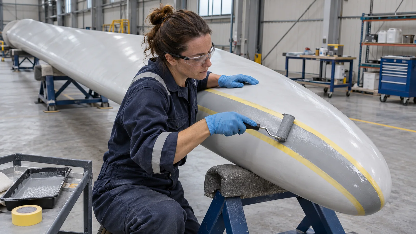
This guide compares the LEP system families, the test evidence behind them and the decision to repair or replace what is already on the blade. Inspection and repair timing for erosion itself are covered in the onshore leading-edge erosion guide. For work on installed blades, Gridinta’s blade and leading-edge repair service uses rope access or suspended platforms; the company maintained 705 wind turbine blades in 2025.
What an LEP system is made of
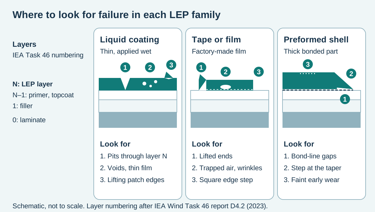
An LEP system is a stack of layers, not a single product. IEA Wind Task 46 numbers the layers from the blade outwards so that damage can be described without brand names: layer 0 is the blade laminate, layer 1 is typically filler or putty, layer N–1 is the primer or topcoat under the protection, and layer N is the outer LEP coating, tape or shell. Its 2023 report on erosion failure modes adds that a leading edge may also carry adhesive layers, edge-sealing layers against water ingress and lightning-protection layers.
The numbering matters to an owner because the layer that damage reaches decides the response. Pits confined to layer N are wear of the protection. Peeling between layer N and the layer below, with that layer left largely intact, is an adhesion failure: Task 46 classes it as failure at the n to n–1 interface and notes that tapes and shells show it as failure of the adhesive. Damage that reaches layer 0 is a blade repair first and a protection question second.
Coatings, tapes and shells side by side
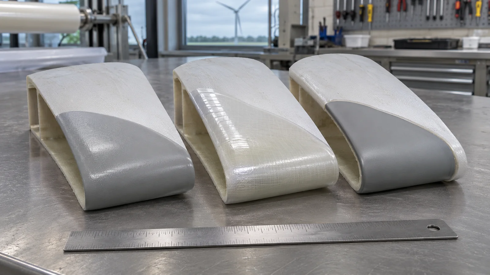
At IEA Wind’s 2020 expert meeting on blade erosion, the options under consideration ranged from liquid coatings and tapes to flexible shells and metallic protection, each forming a different multilayer system on the blade (IEA Wind TEM #98 proceedings). The table lists filler-plus-topcoat rebuilds separately because their job is to restore the profile.
Scroll horizontally to see all table columns.
| System family | Typical use | Strengths | Watch-outs | Repair and inspection |
|---|---|---|---|---|
| Liquid-applied LEP coating | Post-mould factory finish; field repair and retrofit on the outer span | Follows any profile; no tape or shell edges; can be patched locally | Hand application can leave voids and thin spots; cure needs a temperature and humidity window | Patch back to well-bonded coating with a compatible product; pits show most clearly over a contrasting layer |
| Filler plus topcoat rebuild | Restoring lost material and shape before protection goes on | Rebuilds the profile erosion removed | Sits under the LEP layer, not in place of it; a repaired profile may not match the original aerodynamics | Check the profile and the filler-to-laminate bond before the next layer |
| Adhesive tape or film | Outer-span protection, in the factory or as a retrofit | Made in a controlled factory process with few defects; strong erosion resistance when applied properly | Trapped air and wrinkles can cause disbonding; square edges trip the boundary layer | Inspect ends and edges; failure shows as peeling with the layer beneath intact |
| Preformed shell or shield | Thick bonded protection for the highest-speed span | Thick wear layer moulded off the blade; high erosion resistance demonstrated for some designs in laboratory tests | The bond must carry blade bending; metal’s stiffness mismatch risks detachment; ends need a gradual transition | Early wear is harder to see on thick layers; check bond-line ends and transitions |
No family wins on every row. The deciding questions are how fast the blade tip runs, how erosive the site’s rain is, what is already on the blade, and whether the conditions the product needs can be met where the work will be done.
Liquid-applied coatings and filler build-ups
Early protective coatings were rigid epoxy or polyester; they proved inadequate and more ductile materials such as polyurethane took over (Finnegan et al., 2020). Liquid LEP is now typically a flexible polyurethane-type coating over filler and primer. At height it follows a repaired profile without a step and can be patched locally.
Its weakness is that the protection is made on the blade, largely by hand. Herring et al. (2019) note that coatings depend on manual procedures that can leave the defects where erosion starts. DTU researchers found air bubbles in the topcoat of an eroded offshore blade, and in whirling-arm tests a coating with almost no bubbles performed up to 2.6 times better than one with many (Fæster et al., 2021). Mixing, application method and film build therefore belong in the method statement.
Filler rebuilds the material and shape that erosion removed, and the LEP layer goes over it. Task 46’s 2025 report on erosion-safe operation notes that repairs may not fully restore the original blade shape and aerodynamic performance, so check the rebuilt profile against the blade drawing or an agreed template before the protective layer goes on.
Tapes and films
Tapes are made in a controlled factory process, so they arrive with few defects and resist erosion well when applied properly. Herring et al. also identify their failure route: air trapped under the film and wrinkles can lead to disbonding. With tape, application quality moves from mixing and film build to surface preparation, positioning and the bond line.
Tapes also add edges. In wind-tunnel tests on a DU 96-W-180 airfoil, protection tape raised drag by 5–15%, far less than the penalty from erosion (Sareen, Sapre and Selig, 2012). A later model of a 1.5 MW turbine found that standard tapes trip the boundary layer at the tape edge and cut annual energy production (AEP) by 2–3%, while tapered tapes with a step below a critical height had a negligible effect (Major et al., 2021). Ask for the edge profile and the chordwise extent on each side of the blade, not just the product name.
Preformed shells and shields
Shells are moulded protective parts bonded over the leading edge. Because they are made off the blade, they can be the thickest wear layer of the three. Finnegan et al. modelled an 8 m thermoplastic polyurethane component bonded to the outer part of a 13 m blade: near the tip, stress along the bond exceeded the tensile strength of the epoxy adhesive, which the authors flagged for design and manufacture. A shell is only as good as its bond under blade bending; DNV-RP-0573 includes a test programme for delamination caused by blade bending, so ask whether it was run.
Metal shields are the stiffest option. They have shown high resistance in accelerated rain-erosion tests, but their stiffness mismatch with the composite risks detachment (Herring et al., 2019). Transitions matter for every shield: a CFD study of one design found that a gradual transition from shield to blade had no major aerodynamic impact on a multi-megawatt blade, and that the suction side was more sensitive to placement than the pressure side (Kyle, Wang and Forbes, 2020). Thick parts also hide early wear: Task 46 notes that small damage on layers over 1 mm thick may lack the colour contrast that exposes it on thin coatings.
Factory-applied or applied at height
Factory protection comes in two forms. In-mould coatings are painted or sprayed in the mould and are typically rigid, brittle and high-modulus; post-mould systems are flexible multilayer build-ups of filler, primer and coating applied afterwards, and they usually need replacing during the blade’s service life, more often on larger blades (Finnegan et al., 2020). The blade standard IEC 61400-5 (Edition 1.1, consolidated with Amendment 1 in 2025) has a separate subclause for manufacturing and assembly done outside a controlled environment.
At height, the factory’s control has to be rebuilt. ORE Catapult’s 2016 BLEEP review found that paint-based LEP needs stable atmospheric conditions, that temperature and humidity limits can stop coatings curing properly, that high humidity in regions such as the North Sea shortens repair windows for long periods of the year, and that quality assurance is hard to enforce on repairs made by rope access. Plan the window, then record it.
Ask early for the as-built LEP specification and any repair history. Task 46’s 2025 work on inspection data for erosion modelling notes that for older fleets, or blades that have been repaired, the LEP characterisation may vary or be unavailable. If the existing system is uncertain, obtain a preparation and compatibility plan approved by the blade manufacturer or material supplier. Use an agreed trial area to check adhesion before starting the campaign. Before mobilising, take these limits from the product data sheet and write them into the method statement:
- Minimum air and surface temperature for application and for cure.
- Maximum relative humidity and the required margin between surface temperature and dew point.
- Cure time before the rotor can turn, and the overcoat window between layers.
- Surface preparation: cleaning, abrasion, dust removal and the condition to be reached.
- Film build, tape overlap and edge sealing, or shell fit-up and adhesive coverage.
- How sanding dust and removed LEP will be captured, as set out in the blade repair dust and waste containment guide.
In cold months those limits can close the window for weeks; the winter repair windows in our icing article show how to plan around them. Contamination has to come off first, as explained in why blade cleaning and coating matter.
How tip speed and rain climate set the duty
The turbine characteristic that matters most for erosion is the maximum tip speed, which the blade reaches at or above rated wind speed; the higher it is, the faster the erosion (IEA Wind Task 46 report on erosion-safe operation, 2025). In 2018, DTU researchers put the tip speed of many modern turbines at 80 to 90 m/s. NREL’s 2024 rotor research agenda notes that offshore rotors run at higher tip speeds and suffer more erosion than land-based rotors, whose rotor speed is limited by noise (Bortolotti et al., 2024).
Work out your own figure from the turbine data sheet: tip speed (m/s) = 3.14 × rotor diameter (m) × maximum rotor speed (rpm) ÷ 60. For example, a 120 m rotor at 14 rpm gives 3.14 × 120 × 14 ÷ 60, or about 88 m/s. Put that number in the enquiry, because any rain-erosion evidence a supplier offers should relate to it.
Small changes in speed have large effects. In a 2018 concept study, Bech, Hasager and Bak modelled a rotor with a 90 m/s maximum tip speed: its leading edge lasted 1.6 years with no speed reduction, and about 10 years when tip speed was cut to 80 m/s in rain above 10 mm/h and to 70 m/s above 20 mm/h. As of Task 46’s February 2025 report, this erosion-safe operation had not, to the authors’ knowledge, been tested on a turbine, but the sensitivity is the point for LEP selection: the faster the tip, the stronger the evidence you need.
Rain is the main driver; hail does more damage per impact but falls far less often (Task 46, 2025). Damage also concentrates in a few events. A model of a 15 MW reference turbine at a Dutch coastal site attributed roughly half of the erosion damage to only 10% of rain events, with large droplets far more damaging per volume of water (Barfknecht and von Terzi, 2025). Another study found that the choice of drop-size model alone changed calculated blade lifetime 44-fold (Tilg et al., 2022), and Task 46 notes that average wind and rain inputs are likely to predict longer lifetimes than time series. When a supplier quotes an expected life, ask which rain data, drop-size assumption and tip speed it rests on.
How to assess rain-erosion test evidence
The industry’s standard durability test is the whirling-arm rain erosion test, in which coated specimens spin through an artificial rain field. ASTM G73-10 (2021) is the general test method for liquid impingement erosion on rotating apparatus. DNV-RP-0171 (Edition 2018-02, amended 2021-10) identifies the rig details and parameters that influence results and gives guidance on a calibration specimen, so that results from different rigs can be compared.
DNV-RP-0573 (Edition 2020-12, amended 2021-10) is the evaluation step. It covers erosion and delamination caused by rain impact and delamination caused by blade bending, recommends cyclic ageing of specimens, and is intended for estimating durability for maintenance planning and for comparing systems. It does not cover damage from ice, hail, dust or corrosives, damage progression beyond the incubation period, or a method for analysing multi-layer systems. DNV also issues type approvals for erosion protection systems: level 1 on non-degraded specimens and level 2 including long-term degradation to ISO 12944-9 Annex B. The type approval confirms a minimum erosion durability of three years for a simplified design load case.
Why laboratory hours do not convert into field years
- Test conditions. Tests typically last from a few minutes to 30 hours (ORE Catapult, 2016). Whirling-arm impact speeds are typically up to twice real tip speeds, which may cause irrelevant failure modes, and a fixed rain field differs from natural rain (Bech et al., 2018).
- Drop size. Damage depends strongly on droplet diameter, and lifetime models are highly sensitive to how drop size is represented.
- Scope. DNV-RP-0573 evaluates the incubation period; what happens after material loss begins, and hail damage, sit outside it.
- Application quality. A laboratory specimen is made under control and a field repair is not, as the bubble results above show.
- Site. Task 46’s work on inspection data found erosion risk to be highly site-specific.
Use test results to rank products tested on the same rig, at relevant speeds, on a build-up like yours. Then calibrate expectations with your own data: a consistent blade inspection report that records LEP condition by blade, side and radius turns field experience into the evidence laboratory hours cannot supply.
Repair the existing LEP or replace the system?
Start from the inspection finding and the layer it reaches. The table gives the usual response; the blade manufacturer’s instructions and your engineering approval decide the final scope.
Scroll horizontally to see all table columns.
| What you see | Where it sits | Usual response |
|---|---|---|
| Isolated pits or pinholes, LEP firmly bonded around them | Wear within layer N | Local repair with the same or an approved compatible product; log the position to trend it |
| LEP peeling, layer beneath largely intact | Adhesion failure at the N to N–1 interface | Map how far adhesion is lost; widespread loss means removing and replacing the system, not coating over it |
| Tape or shell ends lifting | Adhesive or edge-seal failure | Cut back to a well-bonded area and re-seal or replace the section to the supplier’s procedure; check the edge position and step |
| Erosion through LEP and filler into laminate | Layer 0 reached | Repair the laminate to the approved procedure first, then rebuild filler and LEP |
| The same span fails again soon after repair | System or application does not match the duty | Review application records, tip speed and rain exposure before fitting the same product again |
Changing family is a bigger decision than changing product. Consider it when the same span fails again after a correctly recorded application, when tip speed or site exposure goes beyond what the current system’s evidence covers, or when a tape or shell keeps failing at its edges. Removing the old system, extra cure time and access drive the price; the blade repair cost guide shows how those items add up.
Questions to ask an LEP supplier or applicator
Put these questions in the enquiry and expect written answers. They also help when choosing a wind turbine maintenance company for the work.
- Which product is proposed, and is it approved by the blade manufacturer or confirmed compatible, in writing, with the LEP already on the blade?
- Was the rain-erosion testing done on a rig compliant with DNV-RP-0171, at what impact speed and droplet size, and on what substrate build-up?
- Is there a DNV-RP-0573 evaluation or a type approval, and at which level? Were the specimens aged, and was delamination from blade bending assessed?
- If the site sees hail, what evidence covers it, given that DNV-RP-0573 excludes hail?
- What are the temperature, humidity and dew-point limits, the cure time before the rotor turns, and the action if conditions drift during cure?
- How will the old system be removed, back to what sound edge, and how will dust be contained?
- What edge profile, overlap and chordwise extent on the pressure and suction sides will the finished system have?
- Which checks are made at height on each blade (film build or fit, adhesion, edges, cure), and who signs them off?
- What is the repair procedure for this system later, and which products are compatible with it?
Records to keep after LEP work
LEP work is only as traceable as its records. Keep these for every blade:
- Blade serial number, side, and the radial start and end of each protected or repaired area, with scaled photographs before and after.
- The existing system found, what was removed and what was retained.
- Products, batch numbers and expiry dates for filler, primer, coating, tape, shell and adhesive.
- The surface preparation method and the check that released it for the next layer.
- Air and surface temperature, relative humidity and dew point at the start of each layer and through cure.
- Film build, tape overlap or shell fit checks, adhesion and edge-sealing checks, and the cure time before restart.
- Deviations, re-work and the trigger for the next inspection.
These records slot into the blade repair handover checks and give the next inspector a baseline to compare against. LEP is one part of a turbine’s surface protection; towers, nacelles and foundations are covered in the guide to wind turbine coatings by component.
Leading-edge protection questions from blade owners
How long does leading-edge protection last on a wind turbine blade?
Is LEP tape better than a liquid coating?
Can new leading-edge protection be applied over old LEP?
What is the difference between DNV-RP-0171 and DNV-RP-0573?
Does leading-edge protection reduce a turbine’s power output?
Why do offshore blades need stronger leading-edge protection?
Can leading-edge protection be applied in cold or humid weather?
When should a damaged LEP system be replaced rather than repaired?
Sources
Sources checked on 11 November 2026:
- DNV-RP-0171 Testing of rotor blade erosion protection systems (Edition 2018-02, amended 2021-10)
- DNV-RP-0573 Evaluation of erosion and delamination for leading edge protection systems of rotor blades (Edition 2020-12, amended 2021-10)
- DNV: Tackling leading-edge erosion (type approval and laboratory approval services)
- ASTM G73-10 (2021) Standard Test Method for Liquid Impingement Erosion Using Rotating Apparatus
- IEC 61400-5:2020+AMD1:2025, Wind turbine blades
- IEA Wind Task 46, D4.2 Erosion failure modes in leading edge systems (June 2023)
- IEA Wind Task 46, Potential for erosion safe operation (February 2025)
- IEA Wind Task 46, Use of in-field turbine blade inspection data for modelling rain erosion damage initiation (March 2025)
- IEA Wind Topical Expert Meeting #98 on Erosion of Wind Turbine Blades, proceedings (2020)
- ORE Catapult, Blade Leading Edge Erosion Programme (BLEEP), August 2016
- Herring et al. (2019), The increasing importance of leading edge erosion and a review of existing protection solutions, Renewable and Sustainable Energy Reviews
- Fæster et al. (2021), Rain erosion of wind turbine blades and the effect of air bubbles in the coatings, Wind Energy
- Sareen, Sapre and Selig (2012), Effects of leading-edge protection tape on wind turbine blade performance, Wind Engineering
- Major et al. (2021), Aerodynamics of leading-edge protection tapes for wind turbine blades, Wind Engineering
- Kyle, Wang and Forbes (2020), The effect of a leading edge erosion shield on the aerodynamic performance of a wind turbine blade, Wind Energy
- Finnegan et al. (2020), Development of a numerical model of a novel leading edge protection component for wind turbine blades, Wind Energy Science
- Bech, Hasager and Bak (2018), Extending the life of wind turbine blade leading edges by reducing the tip speed during extreme precipitation events, Wind Energy Science
- Barfknecht and von Terzi (2025), Drop-size-dependent effects in leading-edge rain erosion and their impact on erosion-safe mode operation, Wind Energy Science
- Tilg et al. (2022), Effect of drop-size parameterization and rain amount on blade-lifetime calculations considering leading-edge erosion, Wind Energy
- Bortolotti et al. (2024), The Wind Turbine Rotors of the Future, NREL/TP-5000-86097